- Out-of-Stock


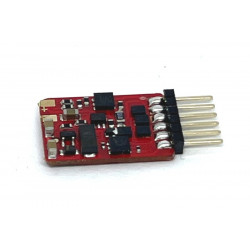
The LoDi-KSM is a simple reverse loop module for the digital model railway. The data format is irrelevant.
 Delivery usually
3-5 working days
The LoDi-KSM is a simple reverse loop module for the digital model railway. The data format is irrelevant.
No contact track is required. Switching takes place in a flash. The module and the connected tracks are also protected against short circuits. The LoDi-KSM is RailCom-capable and forwards the locomotive data to the feedback device via the reversing loop.
In addition, the KSM has a dip switch with which the polarity of the reversing loop can be switched via an externally connected switching decoder.
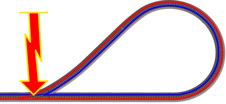
What is a Reverse loop.
Why do you need a reverse loop module on a model railway layout?
Basically, reversing loop modules are only required for the 2-pipe system.
The reversing loop module automatically switches a reversing loop.
A reverse loop is created, as you can see in the picture, when the power supply is crossed when the train is reversing or turning in a section of a circle when it returns to the track.
Here you can now see that the red line crosses the current via the blue line.
This is then called a loop.
In order to avoid a short circuit here, you need a special switch or relay that reverses the polarity of the supply voltage of the track in the reversing loop.
How you are using the device can be seen by scrolling down.
The properties of the LoDi-KSM
1. The LoDi-KSM and its connections.
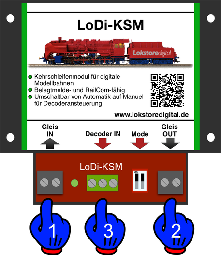
2. Overview of connection details
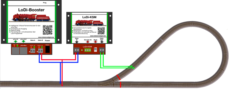
Here you can see the connection variant on a LoDi booster.
All common digital centers and boosters from any manufacturer can be connected to the LoDi-KSM. The module works completely independently.
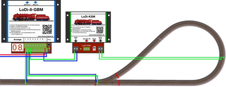
This connection example uses the LoDi-KSM via an occupancy detector.
This is required if you want to report your return loops or report occupied.
Occupancy reporting modules from any manufacturer can be connected to the LoDi-KSM.
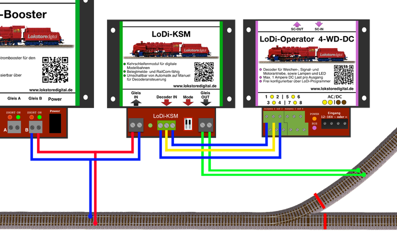
3. Connection to LoDi operator or turnout decoder
As already mentioned, this has
LoDi-KSM a connection for a turnout decoder of any kind.
On the next photo you can see a connection example to a LoDi operator 4-WD-DC.
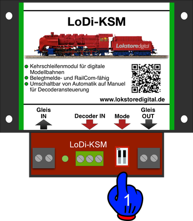
If you now want to switch off the automatic of the module, the two dip switches at (1) must be set to "off". After that, the module can only be controlled via the switch terminals (decoder IN).
The module has 2 operating modes that can be set:
4. Technical data
Dimensions:
Length 8.9 cm
Width 10 cm
Height 3.5 cm
Weight:
83 grams
At the digital terminal, i.e. in digital operation, the decoder can be supplied with up to 22 volts.
! Pay attention to the information provided by the manufacturer of your digital center or booster!
The power supply of the decoder must be done with AC voltage!
Permissible from 12 - 24 volts alternating voltage!
Loadable by consumers with 3 amps for a short time and 2 amps continuously
The LoDi-KSM is a simple reverse loop module for the digital model railway. The data format is irrelevant.